There are three ways to insert 3D models:
- Insert > Multimedia When you use this option, the 3D model is embedded into the topic or snippet. In addition, you can specify advanced settings, such as rendering mode, lighting options, and how to display the model when the output opens.
- Insert > Hyperlink When you use this option, the user must click the text link in order to open the 3D model. Also, you can choose to open the 3D model in another window.
- Drag and Drop You can also insert embedded 3D model files by dragging and dropping the file from the Content Explorer or File List window pane to the XML Editor. However, with this method, you can specify any necessary advanced settings only after the 3D model file is inserted (to do this, right-click on the inserted 3D model and select Edit Multimedia).
[Menu Proxy — Headings — Online — Depth3 ]
How to Insert an Embedded 3D Model
- Open the content file.
- In the XML Editor, place your cursor where you want to insert the 3D model.
-
Select Insert > Multimedia > 3D Model . The Insert Multimedia dialog opens.
Note Depending on where your cursor is located in the XML Editor, you can also right-click and from the context menu select Insert > Multimedia.
- Select the General tab.
-
Select a U3D file to insert. You can do this in various ways.
- To select a U3D file already in the project, select Multimedia in project.
-
Find and choose the file in the Select File area. Use the buttons in the local toolbar to view all files in a list, view files in their folder structure, etc.

Shows all of the files

Shows or hides the folders that the files are stored in.

Shows or hides the files. If you click this button when the Show Folders button
 is selected, the area splits into two. The folder is shown on the left side, and the files and subfolders within it are shown on the right.
If the Show Files button
 is the only one selected, you can click this button to move up one folder level.
Lets you filter the kinds of files shown below. Depending on the task you are performing, this field may already be populated with the most appropriate file type(s).
-
(Optional) To select a U3D file outside of the project, click
 . If you want to select a U3D file that you recently inserted somewhere in your project, click the down arrow in the field next to and select the file from the list.
Note If you select a U3D file outside the project, that file is then copied and placed inside the project. The U3D file is stored in the Resources\Multimedia folder of the Content Explorer.
Note You cannot add U3D files from the web.
-
(Optional) If you want to apply a specific style class to the 3D model, you can select it from the Style Class field. For more information see Styles and Stylesheets.
Example You have created in your stylesheet a class of the MadCap|model3D style called "border" (i.e., MadCap|model3D.border) and you have set the border for all sides of that class to 10 pixels. Rather than using the default parent MadCap|model3D style when you insert the 3D model, you select MadCap|model3D.border from the Style Class drop-down. As a result, 10 pixels are added around the 3D model in the output.
- (Optional) In the Screen Tip field, you can type a phrase that will appear when the end user hovers over the 3D model in the output. If you want to insert a variable in a field, you can click
 . The variable will appear as syntax in the field, but in the output the variable definition will be shown.
 - (Optional) Select the Advanced tab and complete the options as necessary.
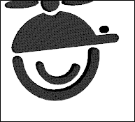
To Set Activation Options
State Select the initial display setting for the 3D model when you open the topic.
- (Default) Displays a gray box where the 3D model is located. If you have selected a background color or image, it will display instead of a gray box. The 3D model activates when you click the box.
- Active on document open The 3D model activates when you open the output.
- Active on page view The 3D model activates when you view the page where it is located. Until you view the page where it is located, the output displays a gray box or the 3D model's assigned background color or image.
- Active on click Displays a gray box where the 3D model is located. If you have selected a background color or image, it will display. The 3D model activates when you click the box.
Note Loading many 3D images at once decreases page and document load speeds. If your content uses many 3D models, you may want to make your 3D models Active on Click to improve performance.
Display 3D Toolbar on Activation When the 3D model activates, the toolbar displays. The toolbar allows you easily to change the model's properties, such as lighting or rendering, when viewing the model in the output.
Note For more information about changing rendering modes using the 3D model toolbar, please refer to the Adobe Acrobat Help.
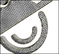
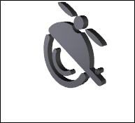
To Set Rendering Options
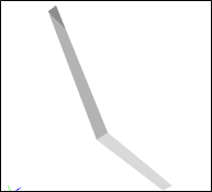
Mode Changes the 3D model's surface.
Default

Wireframe

Solid

Shaded Wireframe
Solid Wireframe
Hidden Wireframe
Transparent

Vertices
Transparent Wireframe

Shaded Vertices
Bounding Box
Illustration
Transparent Bounding Box
Solid Outline

Transparent Bounding Box Outline

Shaded Illustration
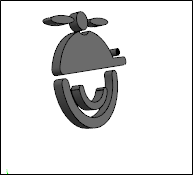
Note: The U3D content above is displayed as image files to ensure compatibility across all devices.
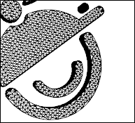
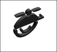
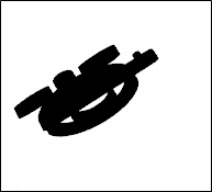
Lighting Change the type of lighting you want to hit the 3D model.
Default
Primary Color Lights

No Lights
Blue Lights
White Lights
Red Lights

Day Lights
Cube Lights
Night Lights
CAD Optimized Lights
Bright Lights
Headlamp

Note: The U3D content above is displayed as image files to ensure compatibility across all devices.
- Background Color Changes the image's background color.
- (Optional) Select the Size tab and complete the options as necessary to resize the container area where the 3D model will be displayed. As an alternative, you can click and drag the icon
 in the lower-right corner of the container.
To Set a Precise Width and/or Height
In the Width and/or Height field of the Size section, provide the settings. First you need to select Length in the top drop-down list. You can then enter a value in the lower-left area and choose from several different units of measurement (points, pixels, centimeters, etc.) in the lower-right area.
To Set the Minimum Width and/or Height
If the original object is smaller than the minimum width or height that is set, it will be enlarged so that it reaches the minimum value. If the original object is larger than the minimum width or height, it will not be resized.
In the Width and/or Height field of the Minimum Size section, provide the settings. First you need to select Length in the top drop-down list. You can then enter a value in the lower-left area and choose from several different units of measurement (points, pixels, centimeters, etc.) in the lower-right area.
To Set the Maximum Width and/or Height
If the original object is larger than the maximum width or height that is set, it will be reduced in size so that it is no greater than the maximum value. If the original object is smaller than the maximum width or height, it will not be resized.
In the Width and/or Height field of the Maximum Size section, provide the settings. First you need to select Length in the top drop-down list. You can then enter a value in the lower-left area and choose from several different units of measurement (points, pixels, centimeters, etc.) in the lower-right area.
Note When resizing objects, you can ensure the aspect ratio is maintained. For example, if you want certain objects to be resized so that each is exactly 3 inches high, you can make sure the width of each object is adjusted accordingly to stay in proportion. To do this, first set the height at 3 inches. You would not set the width property at all. In the same way, if you were to specify an exact width, you could maintain the aspect ratio by not setting the height.
-
(Optional) Select the Position tab and complete the options as necessary to determine how the 3D model is positioned in the topic. You can select a Float and a Clear setting. You can also set the Vertical Alignment of the object.
Float
Use this field to specify where to place the element on the page.
- None Does not place the element in a specific location.
- Left Positions the element on the left side of the page frame, allowing you to type text to the right of the element.
- Right Positions the element on the right side of the page frame, allowing you to type text to the left of the element.
- Center of Column Positions the element in the center of the column on the page.
- Outside Left Margin Positions the element beyond the left margin of the topic text.
- Outside Right Margin Positions the element beyond the right margin of the topic text.
- Outside Frame Positions the element outside of the page frame.
- Outside Frame, Top Align Positions the element outside of the page frame, as well as aligning it with the top of the frame.
- Left of Frame Positions the element to the left of the page frame.
- Right of Frame Positions the element to the right of the page frame.
- Center of Frame Positions the element both vertically and horizontally in the middle of the page frame.
Clear
Use this field to position an element so that it is "clear" of an adjacent element. For example, let's say you have already inserted an element and applied the float left property to it. If you then insert another element immediately after the first element, you want to make sure that the second element doesn't rest next to the first one. Instead, you want the second element to be placed completely below the first one. Therefore, you can apply a clear property to the second element.
- None Does not apply the clear property to the element.
- Left Side The element will be placed below the bottom outer edge of a previous element that is floating left.
- Right Side The element will be placed below the bottom outer edge of a previous element that is floating right.
- Both Sides The element will be placed below the previous one, whether floating left or right.
Vertical Alignment
Use this field to adjust where the item is positioned vertically.
- Baseline The baseline of the box will be aligned with the baseline of the parent box.
- Text Top The top of the box will be aligned with the top of the parent element's font.
- Text Bottom The bottom of the box will be aligned with the bottom of the line box.
- Top The top of the box will be aligned with the top of the line box.
- Middle The vertical midpoint of the box will be aligned with the baseline of the parent box, plus half the x-height of the parent.
- Bottom The bottom of the box will be aligned with the bottom of the line box.
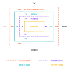
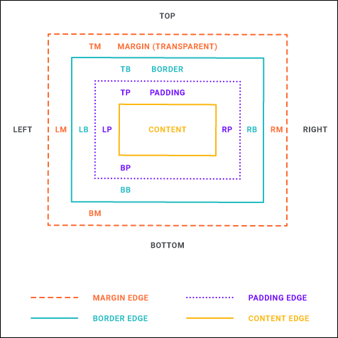
- (Optional) Select the Borders & Margins tab if you want to specify margins, padding, or borders around the 3D model.
Margin
Click in any of the individual fields (Left, Right, Top, Bottom) to specify the settings for the margins around the object. If you click the down arrow to the right of all the fields, the settings will be applied to all of the margin fields.
Padding
Click in any of the individual fields (Left, Right, Top, Bottom) to specify the settings for the padding. In the left side of the field, enter a number for the amount of padding. In the right side of the field, select a unit of measurement (e.g., point, pixel, centimeter) for the number you entered.
Border Radius
- Click in any of the individual fields (Top-Left, Top-Right, Bottom-Right, Bottom-Left) to specify the settings for a particular corner of the table. If you click the down arrow to the right of all the fields, the settings will be applied to all of the fields.
- When you click that down arrow or in one of the individual fields, a small popup displays. This popup has two halves. You can complete only the left side of the popup if you like. This will create a curve that is equal horizontally and vertically. If you want a border to have more of a curve either horizontally or vertically, you can complete the fields in the right half of the popup as well, so that you have two values (e.g., 10px 15px) instead of one. For more information on using two sets of border radius properties, see css3.info/preview/rounded-border/.
- Use the lower-left area of the popup to enter a number for the amount of curve. The greater the number, the more curve that is applied.
- Use the area to the right of the number field to select a unit of measurement (e.g., point, pixel, centimeter).
- If you want to provide a second value for the rounded border, complete the same fields on the right half of the popup.
- When you are finished, click OK in the small popup.
Borders
Click in any of the individual fields (Left, Right, Top, Bottom) to specify the settings for the border. If you click the down arrow to the right of all the fields, the settings will be applied to all of the border fields.
When you click that down arrow or in one of the individual fields, a small popup displays.
- Use the lower-left area of the popup to enter a number for the border thickness.
- Use the lower-middle area to select a unit of measurement (e.g., point, pixel, centimeter) for the number you entered.
- Use the upper-right area to select a color for the border.
- Use the lower-right area to select a line type (e.g., solid, double, dashed) for the border.
- Click OK.
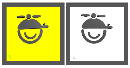
- (Optional) Select the Background tab if you want to add background settings to the 3D model interface. This includes the ability to specify a color, an image, or a repeating pattern for the background image. You will see this image or color when the page loads instead of the gray box that appears by default.
To Set a Color for the Background
In the Color field, click the down arrow and select a color from the popup. For advanced color options, select More Colors and use the fields in the Color Picker dialog.
To Add an Image to the Background
- Next to the Image field, click the Browse button. The Insert Image dialog opens.
- Select an image file to insert and click OK.
- If you want the background image to repeat, select one of the options from the Repeat field. You can also set the image position horizontally and vertically by using the X and Y fields.
Note You may want to use an image of your 3D model as the background image. By doing this, you will see picture of the model instead of the gray box that appears by default.
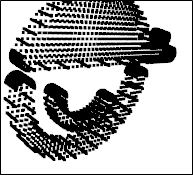
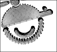
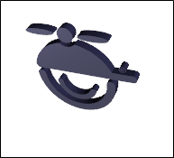
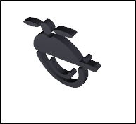
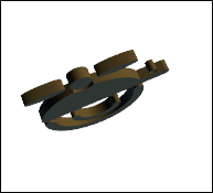
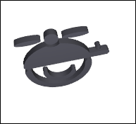
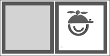
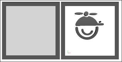
These two images show the same 3D model side-by-side. The one on the left is set to Activate on Click, so it shows a default gray box when the page opens. The one on the right is also set to Activate on Click, but a background image has been set to shows how the model will look it is activated, so you do not see the default gray box.
Note This is different from adding a color to the background, which adds a color behind the model after the 3D model is activated.

- Click OK. The 3D model is added to the topic, represented by a gray square or rectangle, which is the area where the 3D model will be shown in the output.
- Click
") to save your work.
to save your work.
How to Insert an Embedded 3D Model—Drag-and-Drop Method
-
Open the Content Explorer or File List window pane.
If necessary, make sure you float and position the window pane or editor (see Customizing the Workspace) so that you can see both it and XML Editor at the same time.
- Click and drag the 3D model file from the Content Explorer or File List window pane to the location where you want it in the XML Editor and drop it.
- Click to save your work.
How to Insert a 3D Model Link
- Open the content file.
- In the XML Editor, highlight the text that you want to use as the link (or "hotspot") to the movie.
-
Do one of the following, depending on the part of the user interface you are using:
- Ribbon Select Insert > Hyperlink.
- Local Toolbar In the local toolbar of the XML Editor, click
 .
.
The Insert Hyperlink dialog opens.
- From the Link to field select File in Project.
- Navigate to the 3D model that you want to link to and select it.
- (Optional) The Link text field displays the text that you highlighted in the topic, which will be used as the hyperlink. Leave the text as it is, unless you decide you would like to change it. If you want to change the link text, type the new text in the field. It will replace the previously selected text in the topic.
- (Optional) In the Screen Tip field, you can type a phrase that will appear when the end user hovers over the 3D model in the output. If you want to insert a variable in a field, you can click . The variable will appear as syntax in the field, but in the output the variable definition will be shown.
- (Optional) Next to the Style Class field, click the Select button. This opens the Select Class dialog, which lets you apply one of the defined hyperlink styles from your stylesheet to the link. You can change the appearance of the link in the Stylesheet Editor. After you select a style class in the dialog, click OK. The Style Class field displays the selected style. (If you do not specify a style class, Flare uses the parent "a" style.)
-
(Optional) In the Target Frame field, click the drop-down arrow to select the way the linked destination will open (e.g., in another window, in a popup).
- Page Default The destination file opens in the same window as the output window.
- Parent Frame The destination file opens in the parent frame of the current topic while hiding that topic.
- New Window The destination file opens in a new browser window.
- Same Frame The destination file opens in the same window frame as the current topic.
- Top Frame The destination file opens in the same output window, removing all other framesets. You might use this option, for example, if the destination topic has its own frameset.
- Popup Window The destination file opens in a popup box on top of the current topic.
- Click OK. The hyperlink is added to the topic.
- Click to save your work.
What’s Noteworthy?
Note For more information, see Multimedia File Types Supported.
Note You can include 3D models in topics that you send for review. See Reviews and Collaboration and Sending Files for Review in Contributor or Flare.
Note Some browsers do not support U3D files. This is because certain browsers do not support the plug-ins required to play this file type.
Note 3D models will not display if Mark of the Web is enabled. See Adding Mark of the Web.